|
The hardware needed to create a "LArduino" (Linkbot + Arduino) robot is available in the Linkbot Advanced Kit available from Barobo:
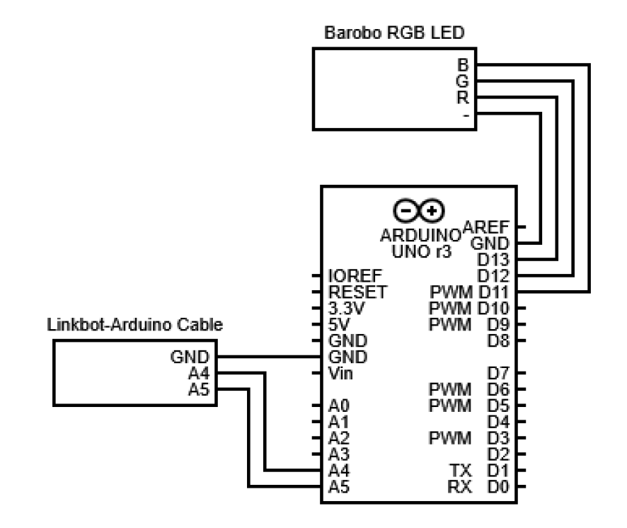
2. Connecting the LED Module to the Arduino The circuit diagram for connecting the LED module to the Arduino is:
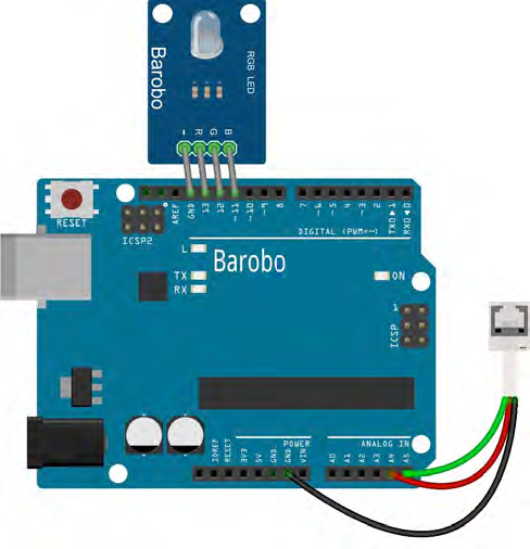
The image below provides another view of the connections. The R, G, and B pins on the LED module plug into digital pins 13, 12, and 11, respectively, on the Arduino, as shown in the first image below. The LED - (ground) pin plugs into the GND pin next to pin 13.
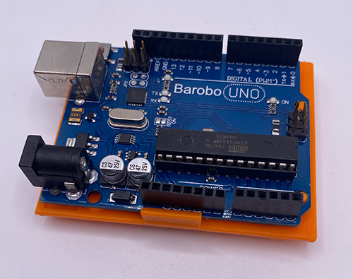
3. Connecting the Arduino to the Linkbot The image above also shows how the green, red, and black wires from the white cable connector plug into the Arduino's A5, A4, and GND pins, respectively. The other end of the white cable plugs into the top of the Linkbot, as shown in the image below (without the LED module installed). 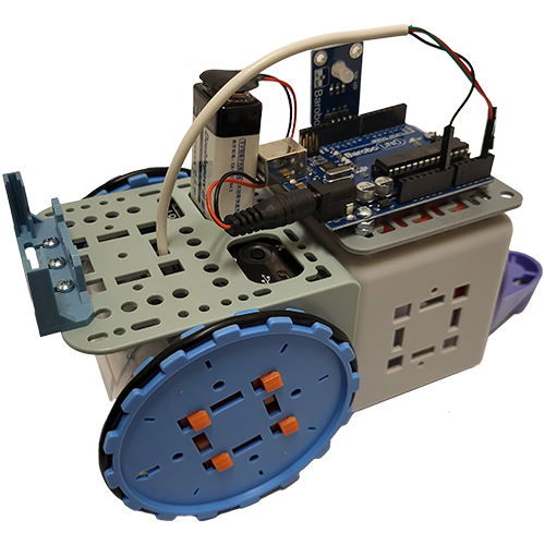 Use the Arduino Holder to attach the Arduino to the Linkbot as shown below. Line up the holes in the Arduino board with the pegs on the holder, then snap the Arduino into place: 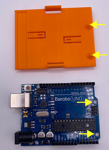
See the lesson on Connect a Hardware Linkbot.
5. IMPORTANT: The Correct Procedure to Turn on Power for Arduino and Linkbot If that happens, disconnect the Arduino from the Linkbot and then plug in the Linkbot charging cable. If the yellow charging light comes on, then you can disconnect the charging cable and should be able to start the Linkbot again and repeat the Arduino connection process, making sure the Arduino is plugged in to the 9V battery before turning on the Linkbot. For more debugging tips, see this lesson.
|